
PRODUCTS / PNEUBEND
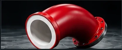
CERAMIC-LINED
PIPE BENDS
Explore proposed sizes, materials, bend angles, connections and technical information for this PneuBend family.
PNEUBEND / ENGINEERING
DN50–DN400
Nominal sizes
30° / 45° / 90°
Angles
Multiple
Standard radii
3
Base metals
TECHNICAL DETAILS
Ceramic-Lined Wear-Resistant Pneumatic Conveying Pipe Bends
Review the complete ceramic-lined pipe bends content below. All specifications and product claims remain subject to approval before publication.
Ceramic Liner and Metal Housing
Ceramic-lined bends use a hard internal product-contact surface within a structural pipe shell. The liner may be formed from tiles, segments or other engineered shapes. Unlike an external ceramic-backed bend, the ceramic is exposed to the conveyed particles from the beginning of operation.
The liner material is not sufficient to define performance: joint design, bonding/retention, impact loading and finished bore need equal attention.
Alumina and Silicon Carbide Liner Options — Pending Validation
Alumina and silicon carbide are established industrial ceramic materials used for wear protection. They are candidates for application discussions, but specific PneuBend ceramic chemistries, purity levels and formulations are not yet approved as stocked options. Any offer will identify the actual material and fabrication route.
Sizes DN50–DN400
Connection sizes are proposed from DN50 through DN400. The shell OD and liner thickness determine the eventual clear bore; the nominal DN is not itself a guaranteed finished ID.
Bend Angles 30°, 45° and 90°
Each proposed angle must be checked against the liner arrangement and wall-impact pattern. Continuous shell curvature does not guarantee a continuous liner surface if the design uses discrete segments.
Fixed Radii and Dimensional Data
| Nominal DN | Compact CLR (mm) | Standard CLR (mm) | Extended CLR (mm) |
|---|---|---|---|
| DN50 | R250 | R500 | R750 |
| DN65 | R300 | R500 | R750 |
| DN80 | R300 | R500 | R750 |
| DN100 | R400 | R750 | R1000 |
| DN125 | R500 | R750 | R1250 |
| DN150 | R600 | R1000 | R1500 |
| DN200 | R750 | R1250 | R2000 |
| DN250 | R1000 | R1500 | R2500 |
| DN300 | R1250 | R2000 | R3000 |
| DN350 | R1500 | R2500 | R3500 |
| DN400 | R1500 | R2500 | R4000 |
Candidate common catalog for the five pipe-based families. Manufacturing and lining feasibility not yet approved. All dimensions in millimetres.
The values are suggested configuration tiers, pending manufacturing approval. Tighter bends may require smaller liner elements or an alternative method, with possible consequences for joint count and impact resistance.
Carbon Steel, AISI 304 and AISI 316 Shells
The outer pipe provides structural support and connections. Choice of carbon steel or stainless steel should reflect corrosion, cleaning, strength and the complete assembly design. A stainless steel shell does not make an unsuitable ceramic or bond chemically compatible.
DIN/ANSI Flanges and Straight Pipe Ends
Plain pipe and flanged ends are proposed. Specify the pipe size standard, flange pattern, liner continuation and gasket surface. The fitted liner and the adjacent pipework should maintain the intended bore and avoid abrupt steps.
Finished Bore and Connection Transition
A dimensional drawing must separately identify shell OD, nominal connection size, liner thickness, minimum finished bore, internal steps and transitions. This is essential for calculating local velocity, avoiding plugging and verifying fit.
Cleaning, Impact and Liner Integrity
Ceramics are hard but can be vulnerable to impact, thermal shock or improper assembly. Confirm the particle size distribution, possibility of foreign objects, operating cycles, and cleaning methods. Monitor liner joints and the downstream pipe, not only the steel casing.
Technical Quotation
| Parameter | Proposed launch configuration |
|---|---|
| Family | Ceramic-Lined Pipe Bend |
| Geometry | Pipe shell with internal ceramic protection |
| Nominal size | DN50–DN400 |
| Flow deflection | 30°, 45°, 90° |
| Base materials | Carbon steel; AISI 304; AISI 316 shell |
| Connections | Plain pipe; EN/DIN flange; ANSI/ASME flange |
| Bend radius | Several proposed CLR tiers per size; exact liner feasibility to be confirmed |
Availability, actual finished bore, wall thickness, pressure/temperature limits, flange drilling, mass and accepted manufacturing combinations are confirmed on an approved quotation and drawing.
Compare product families · Request a ceramic-lined bend quote.
ENGINEERED FOR YOUR PROCESS
HAVE A CONVEYING CHALLENGE?
Share your material, dimensions and operating conditions. Our team can review the proposed bend configuration.