
PRODUCTS / PNEUBEND
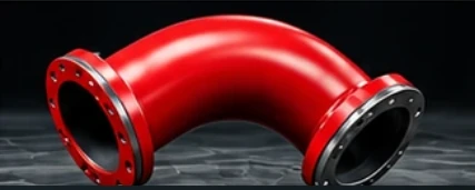
SWEEP-TYPE
BENT PIPE
ELBOWS
Explore proposed sizes, materials, bend angles, connections and technical information for this PneuBend family.
PNEUBEND / ENGINEERING
DN50–DN400
Nominal sizes
30° / 45° / 90°
Angles
Multiple
Standard radii
3
Base metals
TECHNICAL DETAILS
Sweep-Type Bent Pipe Elbows for Pneumatic Conveying
Review the complete sweep-type bent pipe elbows content below. All specifications and product claims remain subject to approval before publication.
Continuous Curved Flow Path
A sweep elbow redirects the conveying stream through a continuous curved pipe. The centerline radius determines how far the turn extends and influences particle-wall contact, pressure behavior and the installation space required. A longer radius is not universally gentler or more wear-resistant: it can increase sliding distance, which matters for some polymer resins and sticky materials.
PneuBend’s proposed sweep program has three standard deflections and several preferred radii for each nominal pipe size. These are selection starting points pending approval of bending tools, wall thinning limits and actual material availability.
Sizes DN50–DN400
Nominal sizes cover DN50, DN65, DN80, DN100, DN125, DN150, DN200, DN250, DN300, DN350 and DN400. An order must specify the actual tube or pipe OD, wall thickness and finished clear bore. Identical DN labels do not guarantee the same OD across EN tube, NPS pipe and proprietary conveying systems.
Available 30°, 45° and 90° Bends
The stated angle is the change in flow direction. If a straight tangent is required at the inlet or outlet, its length is specified separately. A 90° sweep generally needs more room than a 30° sweep at the same radius, but installation envelopes also depend on extensions and connection hardware.
Fixed Centerline Radius Choices for Each Diameter
| Nominal DN | Compact CLR (mm) | Standard CLR (mm) | Extended CLR (mm) |
|---|---|---|---|
| DN50 | R250 | R500 | R750 |
| DN65 | R300 | R500 | R750 |
| DN80 | R300 | R500 | R750 |
| DN100 | R400 | R750 | R1000 |
| DN125 | R500 | R750 | R1250 |
| DN150 | R600 | R1000 | R1500 |
| DN200 | R750 | R1250 | R2000 |
| DN250 | R1000 | R1500 | R2500 |
| DN300 | R1250 | R2000 | R3000 |
| DN350 | R1500 | R2500 | R3500 |
| DN400 | R1500 | R2500 | R4000 |
Candidate common catalog for the five pipe-based families. Manufacturing and lining feasibility not yet approved. All dimensions in millimetres.
The table is a candidate catalog; not all entries are proven bendable for every material and wall thickness. A request outside the chosen range may be evaluated as a custom design rather than shown as a standard stock product.
R/D Ratio
The engineering ratio R/D is meaningful only when D is clearly defined. In early comparisons the nominal DN may be used for screening, but approved documents must state whether D is actual OD or finished bore.
Carbon Steel, AISI 304 and AISI 316
Carbon steel provides an economical structural option where corrosion resistance and surface wear requirements permit. AISI 304 and AISI 316 stainless steel are options for specified material-contact or corrosion requirements. Material certificate, surface finish and any post-bend treatment must match the selected construction.
Straight Pipe Ends and Flanged Versions
Plain pipe-end models require OD, wall, end preparation and tangent lengths. Flanged models require the actual approved connection dimensions; both EN/DIN and ANSI/ASME flange patterns are proposed. A flange pattern does not establish the safe working pressure of the complete bend.
Pipe Bending and Fabrication
The fabrication route must account for bend-induced wall thinning, ovality, weld seam location where applicable and any downstream welding or surface treatment. For critical installations, define acceptable tolerances and inspection methods before production.
Dimension Drawing and Radius Table
| Parameter | Proposed launch configuration |
|---|---|
| Family | Sweep-Type Bent Pipe |
| Geometry | Continuously curved pipe |
| Nominal size | DN50–DN400 |
| Flow deflection | 30°, 45°, 90° |
| Base materials | Carbon steel; AISI 304; AISI 316 |
| Connections | Straight pipe ends; EN/DIN flanged; ANSI/ASME flanged |
| Bend radius | Several fixed nominal CLR options per DN, pending tooling approval |
Availability, actual finished bore, wall thickness, pressure/temperature limits, flange drilling, mass and accepted manufacturing combinations are confirmed on an approved quotation and drawing.
An approved drawing should show centerline radius, tangent lengths, angle, OD, wall, total projection, flange-face locations and finished bore. Read the radius guide.
Application Review and Request a Quote
Describe the solids conveyed, velocity or gas flow, solids throughput, pressure/vacuum and expected wear or quality constraints. For a replacement, include measured current CLR and the outlet pipe condition. Start a sweep-bend enquiry.
ENGINEERED FOR YOUR PROCESS
HAVE A CONVEYING CHALLENGE?
Share your material, dimensions and operating conditions. Our team can review the proposed bend configuration.