
PRODUCTS / PNEUBEND
POCKET-TYPE
MATERIAL-CUSHION
ELBOWS
Explore proposed sizes, materials, bend angles, connections and technical information for this PneuBend family.
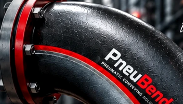
PNEUBEND / ENGINEERING
DN50–DN300
Nominal sizes
45° / 90°
Deflection
Flanged
DIN / ANSI pattern
4
Cast material options
TECHNICAL DETAILS
Pocket-Type Material-Cushion Pneumatic Conveying Elbows
Review the complete pocket / material-cushion elbows content below. All specifications and product claims remain subject to approval before publication.
Product Overview and Main Features
PneuBend pocket elbows change the direction of a solids-conveying line inside a compact cast body. The key distinction from a conventional sweep is the internal pocket or chamber: in a suitable application, conveyed solids can occupy a region around the impact zone and alter how incoming particles contact the wall. The compact flanged construction shown in the PneuBend archive is one configuration within this family.
The pocket mechanism does not mean every material will form a stable protective layer. Material flow properties, moisture, conveying mode, startup behavior and orientation all require evaluation. Pressure loss, residual product and product degradation are part of the selection, not afterthoughts.
How the Material Pocket Works
Material Accumulation in the Chamber
The chamber geometry differs from the smooth, constant-bore curve of a sweep. As particles enter, the geometry can encourage a local build-up of conveyed material. Subsequent particles may then interact with that layer instead of striking the metal directly. The actual mechanism for each casting will be documented with an approved cross-section.
Particle Impact and Flow Redirection
The outgoing stream must remain compatible with the downstream pipe. Compare both elbow-wall wear and outlet-pipe erosion; shifting wear downstream is not necessarily an improvement.
Retention and Cleaning
A pocket can retain solids after conveying stops. This requires particular attention for sticky material, frequent color changes, food applications or processes with strict cross-contamination limits. Ask what evidence supports the cleaning procedure for the material and orientation concerned.
Available 45° and 90° Flow Deflections
Two cast directional-change configurations are planned: 45° and 90°. These values describe the change in the pipe direction, not the internal included angle of an old drawing. The selected configuration requires its own envelope and flange-position drawing.
Nominal Sizes DN50–DN300
| Nominal pocket-elbow sizes | Available proposed angles | Connections |
|---|---|---|
| DN50 | 45° / 90° | Flanged only |
| DN65 | 45° / 90° | Flanged only |
| DN80 | 45° / 90° | Flanged only |
| DN100 | 45° / 90° | Flanged only |
| DN125 | 45° / 90° | Flanged only |
| DN150 | 45° / 90° | Flanged only |
| DN200 | 45° / 90° | Flanged only |
| DN250 | 45° / 90° | Flanged only |
| DN300 | 45° / 90° | Flanged only |
Actual finished bore, flange drilling, pressure rating and casting dimensions depend on the approved model.
Nominal DN is a size reference. The final quotation must give the exact finished bore, machined flange connection, pipe mating dimensions, casting weight and installation envelope. Markings on existing castings are not a substitute for verified dimensions.
Cast Body Materials
Cast Carbon Steel
Proposed for duties where a cast steel housing is appropriate. Specify the approved casting standard, mechanical properties, surface treatment and allowable operating limits for each size.
Cast Aluminium
An option when low mass and process compatibility favor aluminium. Specify the alloy and casting method, and separately verify flange strength, abrasion, temperature and static-electricity requirements.
Cast 304-Type and 316-Type Stainless Steel
For corrosion or material-contact considerations. Engineering drawings should identify the actual casting grade, such as CF8 for 304-type or CF8M for 316-type where applicable, rather than only applying a wrought AISI label to a casting.
Flanged Connections: EN/DIN and ANSI/ASME Patterns
This family is flanged only. Proposed European options use applicable EN flange standards (EN 1092-1 for steel and EN 1092-4 for aluminium); American options reference ASME B16.5 patterns where relevant. The supplier must confirm flange facing, bolt circle, drilling, material and pressure capability of the entire elbow assembly. A PN or Class bolt pattern alone is not an assembly pressure rating.
Dimensions and Flange-Face Offsets
Pocket elbows normally have no meaningful true circular centerline radius. Use a model-specific drawing to specify inlet/outlet centerline offsets, face-to-center distances, connection plane, overall projection, wall thickness and space for removal. Do not substitute a short-radius sweep drawing.
Technical Data and Installation Orientation
| Parameter | Proposed launch configuration |
|---|---|
| Family | Pocket / Material-Cushion |
| Geometry | Cast material-pocket chamber |
| Nominal size | DN50–DN300 |
| Flow deflection | 45° and 90° |
| Base materials | Cast carbon steel; cast aluminium; cast 304-type or 316-type stainless |
| Connections | Flanged: EN/DIN-pattern or ANSI/ASME-pattern |
| Bend radius | Not applicable; use envelope and offsets |
Availability, actual finished bore, wall thickness, pressure/temperature limits, flange drilling, mass and accepted manufacturing combinations are confirmed on an approved quotation and drawing.
For every RFQ, include the material, conveying mode, normal and maximum pressures, temperature, design standards, installation orientation and required cleaning method. Operating pressure and temperature limits are established by the approved design, not copied from flange standards.
Suitable Applications and Limitations
Pocket elbows may be considered for abrasive powders, granules or pellets when the product and operating sequence are compatible with the chamber. They are not automatically preferable for cohesive, moisture-sensitive or frequent-changeover products. A pilot comparison may measure elbow and downstream wear, pressure demand, retained product and fines.
Photographs, Drawings and Downloads
View identified photographs in the product gallery and request the approved casting cross-section, connection drawing, material certificate and installation document for the exact model. Until released, dimension sketches in this preview are illustrative only.
Request a Pocket Elbow Quote
Select the material, DN, 45°/90°, flange standard and operating conditions. Supply existing elbow photographs or the adjacent pipe drawing for a replacement. Request a quote · How to measure.
ENGINEERED FOR YOUR PROCESS
HAVE A CONVEYING CHALLENGE?
Share your material, dimensions and operating conditions. Our team can review the proposed bend configuration.