
PNEUMATIC CONVEYING ELBOWS & PIPE BENDS
PRODUCTS
OVERVIEW
Explore pneumatic conveying elbows and pipe bends engineered around abrasive materials, operating conditions and system layout. The right bend is selected for the process—not just the pipe diameter.
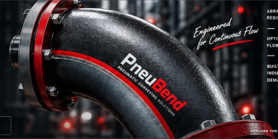
PNEUBEND / ENGINEERING
OUR PRODUCTS
PNEUMATIC CONVEYING ELBOWS AND PIPE BENDS
Engineered for your process. Explore all six initial product families and discuss materials, size and wear-protection options with our team.
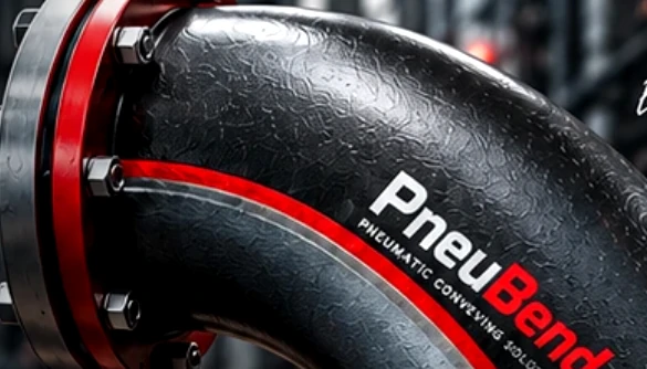
01
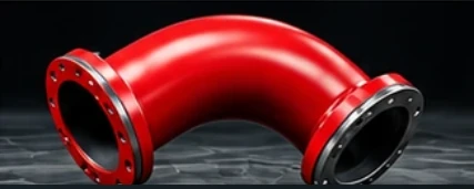
02

03
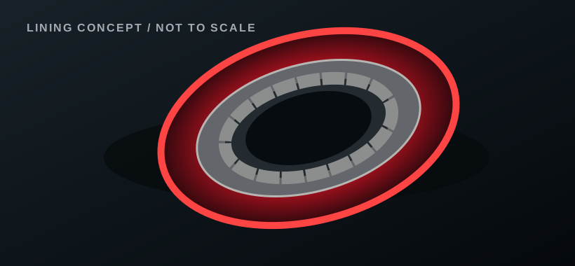
04
05
06
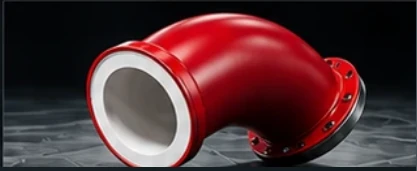
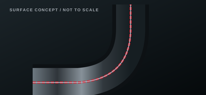
Visual assets in this offline concept are illustrations extracted or adapted from the approved design reference, not certified photographs or technical drawings for each model.
TECHNICAL DETAILS
Pneumatic Conveying Bends and Elbows
Review the complete all products content below. All specifications and product claims remain subject to approval before publication.
Explore the PneuBend Product Range
There is no single elbow geometry or wear material that suits every pneumatic conveying line. Our range is organized by flow-path construction and wear protection so that purchasers can identify a product family quickly, while engineers can compare relevant design differences.
The six product families below form the initial PneuBend launch program. Each family has selectable sizes, angles, materials and connections; manufacturing availability is confirmed by configuration.
Pocket / Material-Cushion Elbows
A cast chamber provides a region in which conveyed material can form a protective cushion in suitable duty. The compact flanged elbow is a version of this family, not a separate product type. Proposed range: DN50–DN300, 45°/90°, cast carbon steel, cast aluminium and 304-/316-type stainless castings. Flanged only. View pocket elbows.
Sweep-Type Bent Pipe Elbows
A continuously curved pipe changes direction along a specified centerline radius. Suitable for applications where the geometry, material-contact surface and bending process can be coordinated. Proposed DN50–DN400, 30°/45°/90°; carbon steel, AISI 304 or AISI 316; straight or flanged ends. View sweeps.
Segmented Pipe Elbows
Multiple straight pipe segments are cut and welded to form the required change in direction. The number and angle of segments matter for internal transitions and fabrication. Proposed DN50–DN400 with the same angle, material and end-connection program as sweep bends. View segmented bends.
Basalt-Lined Pipe Bends
Wear-protected pipe bends using a basalt-based internal layer. Selection must include the actual liner construction, bond/retention design, liner thickness and usable finished bore. Proposed DN50–DN400 and 30°/45°/90°. View basalt-lined bends.
Ceramic-Lined Pipe Bends
A hard ceramic contact surface is installed within a structural metal shell. Ceramic formulation and liner configuration must be selected for the material, impact regime and operating envelope. Proposed DN50–DN400 and 30°/45°/90°. View ceramic-lined bends.
Tungsten Carbide Hardfaced Pipe Bends
A qualified tungsten-carbide-containing weld overlay is intended to protect selected product-contact surfaces. Deposit formulation, thickness, coverage and compatibility with the underlying material require technical confirmation. Proposed DN50–DN400 and 30°/45°/90°. View hardfaced bends.
Compare Product Families
| Product | Geometry or primary protection | Nominal size | Angles | End connections |
|---|---|---|---|---|
| Pocket elbows | Cast material-cushion chamber | DN50–300 | 45°, 90° | Flanged only |
| Sweep elbows | Continuous curved pipe | DN50–400 | 30°, 45°, 90° | Plain or flanged |
| Segmented elbows | Fabricated pipe segments | DN50–400 | 30°, 45°, 90° | Plain or flanged |
| Basalt-lined | Basalt internal protection | DN50–400 | 30°, 45°, 90° | Plain or flanged |
| Ceramic-lined | Ceramic internal protection | DN50–400 | 30°, 45°, 90° | Plain or flanged |
| WC hardfaced | Weld-applied wear overlay | DN50–400 | 30°, 45°, 90° | Plain or flanged |
A lining or overlay is a construction choice, not necessarily a unique flow path. A lined bend may be sweep-shaped or segmented depending on the approved design. Open the detailed comparison.
Choose Diameter, Bend Angle and Connection
Provide the actual outside diameter, wall thickness and end-connection requirement—not just DN or NPS. For lined bends, specify whether DN refers to the nominal connecting pipe or the required finished clear bore. Connection guide · Bend radius guide.
Request a Quotation
Choose a product family, enter the known dimensions and process conditions, and attach existing drawings where possible. Missing data can be marked as unknown for follow-up. Start an RFQ.
ENGINEERED FOR YOUR PROCESS
HAVE A CONVEYING CHALLENGE?
Share your material, dimensions and operating conditions. Our team can review the proposed bend configuration.